【研究背景】
與商業(yè)層狀正極材料相比,富鋰錳基層狀氧化物正極因其極高的容量,以及富錳所帶來的可持續(xù)性和經濟優(yōu)勢,展現(xiàn)出成為下一代高能量密度鋰離子電池正極材料的巨大潛力。富鋰正極的高容量源于過渡金屬層中的額外鋰(即 Li[TM]) 形成Li-O-Li構型,從而觸發(fā)陰離子氧化還原活性。然而,大量脫出Li[TM]會引發(fā)過渡金屬層內不可逆/有害的局部結構重排,包括聚集的空位和O dimer的形成,導致電池長期運行中出現(xiàn)快速的電壓衰減,從而阻礙了富鋰正極材料的實際應用。
在此情況下,為了減輕大量Li[TM]脫出的不利影響,我們提出了一種氧堆垛工程策略,作為限制富鋰正極中Li[TM]遷移的有效方法。具體而言,該策略涉及將傳統(tǒng)的共邊構型(堿金屬層內所有八面體與相鄰過渡金屬層內的八面體均以共邊方式連接)轉變?yōu)樘赜械墓裁鏄嬓停@種構型具有限制Li[TM]遷移的潛力。遺憾的是,這種亞穩(wěn)態(tài)的共面構型只能通過使用鈉基P型(P:棱柱狀堿金屬位點)正極前驅體的非煅燒鈉-鋰離子交換方法獲得。基于以上,出現(xiàn)了兩個關鍵挑戰(zhàn):
(I)雖然已知在離子交換反應過程中,通過TMO?層的滑移,會發(fā)生從棱柱狀NaO?到八面體LiO?配位構型的轉變,但每層TMO?層滑移方向的內在隨機性不可避免地給所得鋰基O型(O:八面體堿金屬位點)結構的氧堆垛引入了顯著的不確定性。
(II)雖然共面構型在緩解由Li[TM]脫出后的空位引起的TM層內結構重排方面顯示出希望,但目前尚無研究提出并證實這種特定的共面構型與Li[TM]脫出/嵌入行為之間的直接關聯(lián)。
因此,有必要對具有共面構型的離子交換O型結構進行進一步的系統(tǒng)研究,以開發(fā)一種旨在錨定Li[TM]以增強富鋰層狀氧化物正極結構穩(wěn)定性的有效氧堆垛工程策略。
【工作簡介】
近日,廈門大學喬羽課題組等以P2-Na0.66[Li0.22TM0.78]O2(NLMO)為前驅體,我們證明了在鈉-鋰離子交換過程中,TMO?層發(fā)生隨機滑移,導致形成了具有O2/O6共生結構的Li0.66[Li0.22TM0.78]O2(LLMO),這與通常公認的理想O2相有本質區(qū)別。盡管TMO2層滑移具有隨機性,但已證實,在這種富鋰正極中成功獲得了具有功能的堿金屬層AMO6八面體與TMO6八面體之間的共面連接構型,顯著抑制了Li[TM]的層間遷移。相應地,TM層內不可逆的局部結構重排,包括聚集空位和與之相關的O dimer的形成,得到了有效緩解。最終,與典型的O3型錳基富鋰正極(Li2MnO3)相比,我們合成的具有O2/O6共生結構的富鋰正極提供了270 mAh/g的高容量以及顯著增強的容量/電壓保持率。
【內容表述】
本研究中揭示了兩個重要問題:
(I) 關于離子交換反應過程中TMO2層滑移導致堆垛層錯的理解仍停留在理論層面,缺乏具體的原位結構實驗驗證。首次,結合變溫XRD和SAED圖譜,我們捕獲了大量TMO2層同時且隨機滑移的直接實驗證據,并識別了堆垛層錯形成的具體結構演化階段,推動了對鈉-鋰離子交換機制的深入理解。
(II) 特定的共面構型對Li[TM]遷移率以及TM層內相關局部結構重排的影響是一個未解決的研究空白。首次,通過結合?Li固態(tài)核磁共振波譜和理論計算,我們證明了在AMO6和TMO6八面體之間的功能性共面構型內,Li[TM]的層間遷移得到了有效抑制,為解決富鋰正極中TM層內無序問題提供了一條新途徑。此外,采用高空間分辨率的多層電子疊層衍射成像技術和RIXS表征,我們證實了TM層內納米尺寸聚集空位及相關O dimer的形成被成功抑制,建立了一個可視化正極結構的研究范式。
總之,這項工作通過調控Li[TM]的脫出行為,為減輕TM層內有害的局部結構重排提供了一種有前景的新方法,可用于高性能的具有陰離子氧化還原活性的鋰/鈉離子層狀氧化物正極。在更廣泛的背景下,本研究中引入的限制Li[TM]遷移的思想不僅限于目前采用的氧堆垛工程策略,還可以進一步擴展到其他結構改性設計,如特定元素摻雜/取代、納米尺度域釘扎以及儲能材料中的局域無序調控。
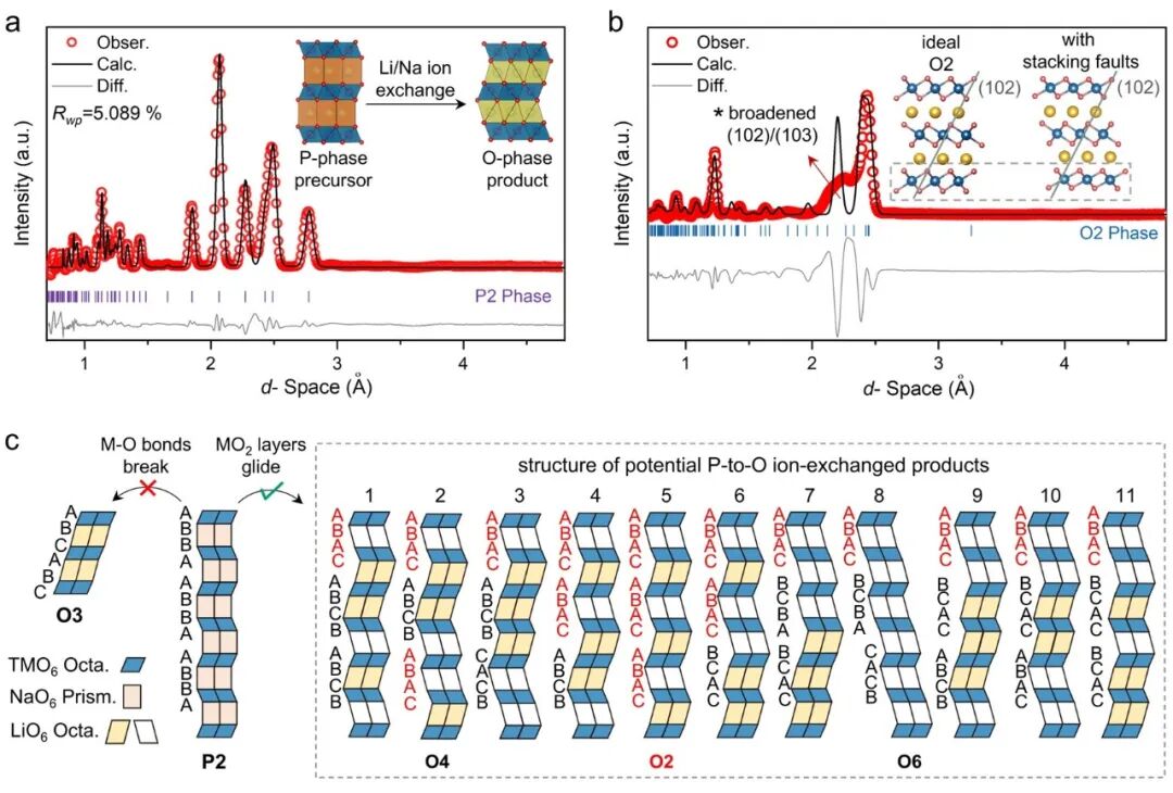
Figure 1. a) Refined NPD patterns of P2 phase precursor (NLMO). b) Refined NPD patterns of ion-exchanged product (LLMO). c) The schematic illustrations of potential ion-exchanged product structures arising from random TMO2 layer gliding in ion exchange reactions.
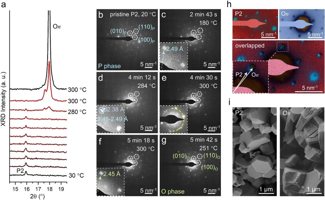
Figure 2. a) Variable-temperature XRD patterns revealing the P-to-O phase transition in the ion exchange reaction of P2 Phase NLMO with Li salts. b–g) In situ SAED patterns along the [001] direction of a mixture of P2 phase NLMO and Li salts, captured during heating up to 300 °C. h) The overlapped experimental SAED patterns of pristine P2 phase NLMO and ion-exchanged On phase LLMO. i) SEM images of P2 phase NLMO and On phase LLMO.
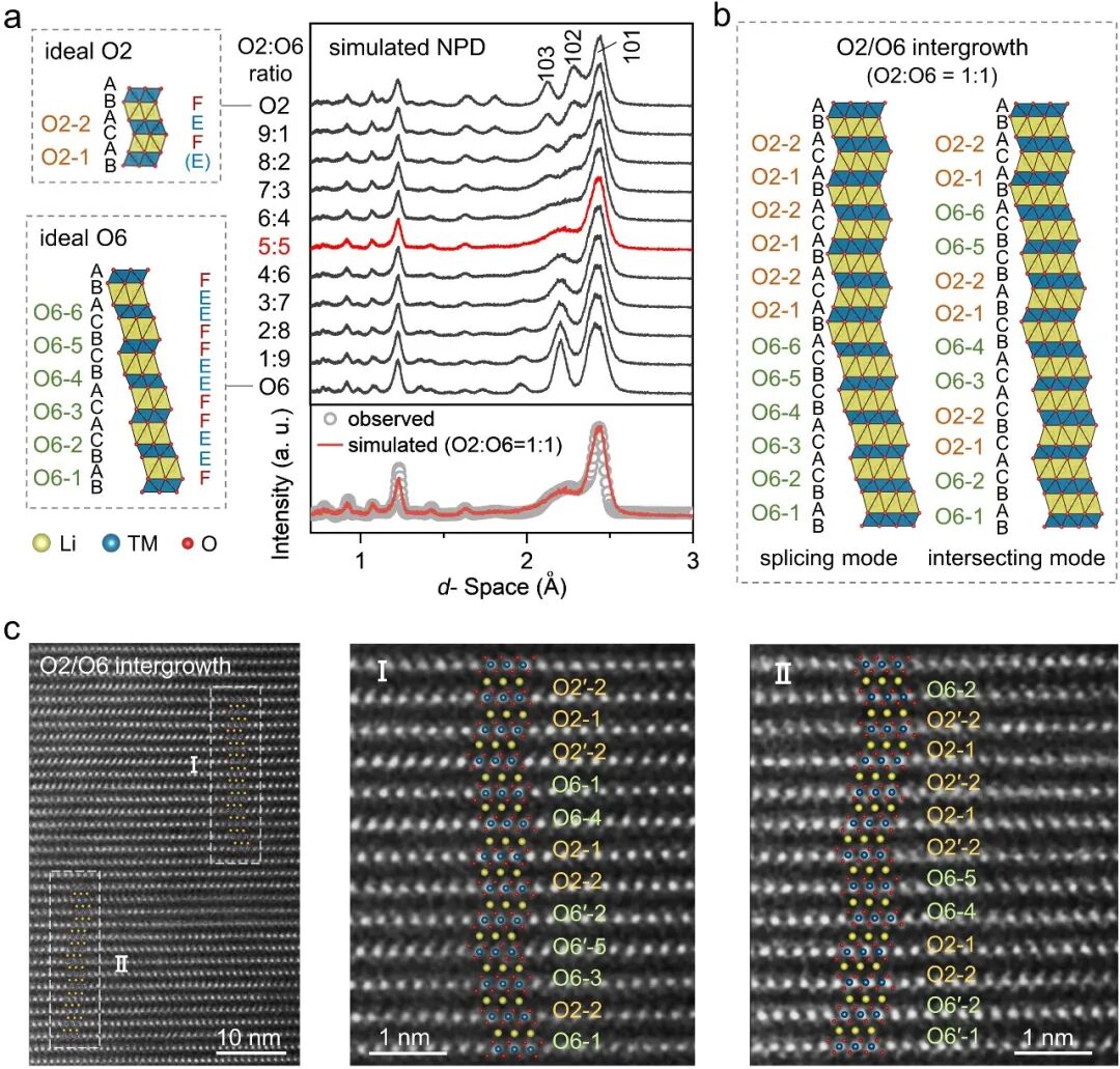
Figure 3. a) Simulated NPD patterns of O2/O6 intergrowth with varying ratios using the FAULTS program. b) Schematic illustrations of the crystal structures representing potential O2/O6 intergrowth phases at a 1:1 ratio, showcasing two representative splicing and intersecting modes. c) HAADF-STEM images of the ion-exchanged product.
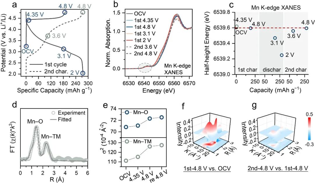
Figure 4. a) The 1st cycling and the 2nd charging curves of O2/O6 intergrowth LLMO in Li half-cells under the current density of 10 mA g?1 for 2–4.8 V. b) Normalized XANES spectra of the Mn K-edge at different SoCs. d) The k3-weighted Mn K-edge EXAFS fitting for the 1st shell Mn–O bond and the 2nd shell Mn–TM bond. e) The Debye-Waller factor (σ2) evolution of Mn–O and Mn–TM bond. f, g) Color 3D WT-EXAFS showing spectral distinctions between f) the OCV and the first charged state, and between g) the first and second charged states.
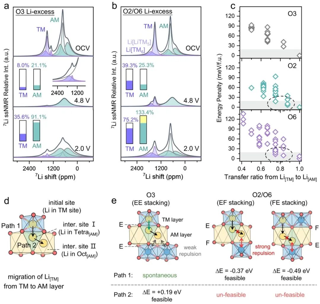
Figure 5. 7Li pj-MATPASS NMR spectra of a) conventional O3 Li-excess and b) O2/O6 Li-excess at OCV, initial charged and discharged state. c) The calculated energy penalty of O3, O2, and O6 unit cells with varied Li[TM]/Li[AM] compositions. d) Calculation of key parameters including sites and pathways for the migration of Li[TM] from the TM layer to the AM layer. e) The calculated energy of Li[TM] migration path in different oxygen stacking modes, and the corresponding schematic illustrations.
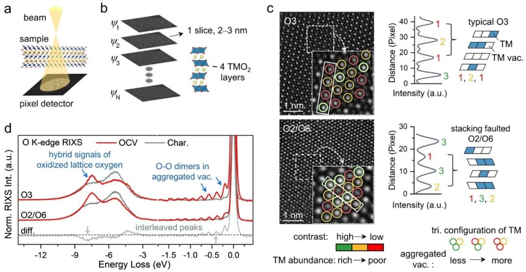
Figure 6. a) Experimental setup for multi-slice electron ptychography (MEP). b) Selected Slice from MEP Reconstruction. c) Selected slices from MEP images of charged O3 Li-excess and O2/O6 Li-excess along the [001] zone axis. d) O K-edge RIXS spectra of O3 and O2/O6 Li-excess at OCV (gray lines) and charged (red lines) states.
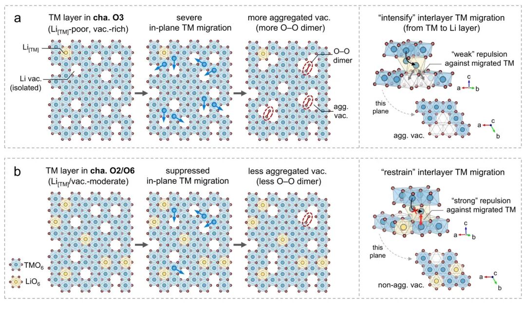
Figure 7.Schematic illustrations of structural rearrangements within TM layers after in-plane TM migration in charged a) O3 and b) O2/O6 Li-excess, and the impact of the corresponding regions on interlayer TM migration.
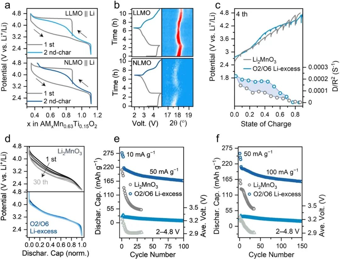
Figure 8. a) The charge-discharge curves of LLMO and NLMO assembled in Li-based half-cells. b) In-situ XRD pattern of the main peak for LLMO and NLMO in Li-based half-cells. c) The GITT results and d) discharge voltage curves over several cycles for O2/O6 Li-excess and Li2MnO3.e, f) Discharge capacity hysteresis and the corresponding average voltage against cycle numbers profiles of O2/O6 Li-excess and Li2MnO3 at the current density of e) 50 mA g?1 and f) 100 mA g?1.
【文獻詳情】
Regulating Li Extraction in Transition Metal Layer for High-Performance Li-Excess Layered Oxide Cathode with Intergrowth Structure
https://advanced.onlinelibrary.wiley.com/doi/10.1002/adma.202520981
DOI:10.1002/adma.202520981